
Refrigerant Leak Detection Methods for HVAC & A/C Techs

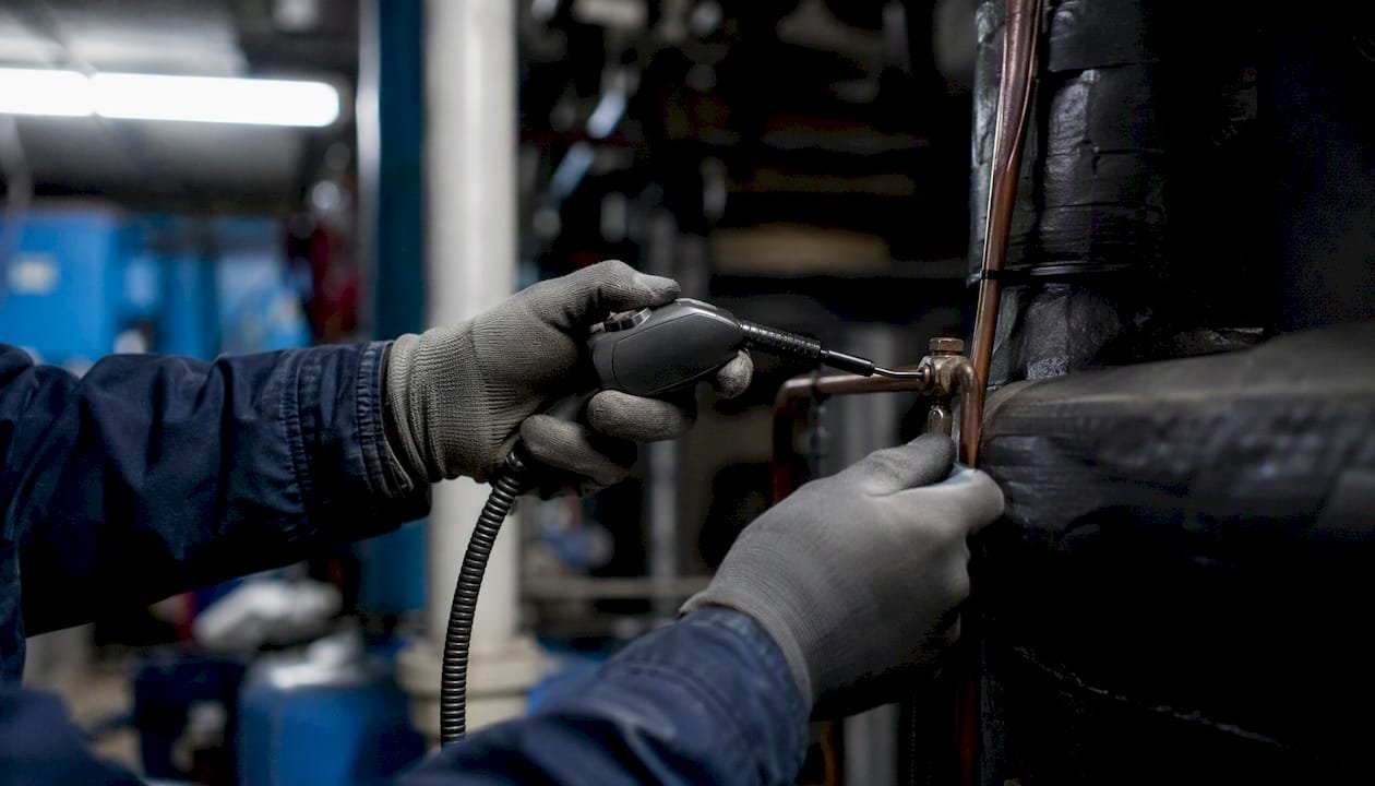
For on-site refrigerant leak locating, use a tiered approach: start with an electronic sniffer (heated-diode or infrared), narrow the location with UV fluorescent dye, ultrasonic detection, or tracer gas, then verify every repair with a nitrogen pressure/decay test. That last step is not optional — it is the code-compliant verification method recognized under 40 CFR 84.106 and aligned with EPA guidance. Beginning January 1, 2026, EPA leak repair rules apply to appliances carrying 15 pounds or more of HFCs or certain substitutes, with defined leak-rate thresholds, repair timelines, and inspection schedules.
Your five go-to methods on site:
- Electronic refrigerant detector (heated-diode or IR): fastest first sweep
- UV fluorescent dye: precise localization on small or slow leaks
- Ultrasonic detector: best on high-pressure escapements and noisy environments
- Tracer gas (helium or hydrogen blend): finds micro-leaks in concealed piping
- Bubble/soap solution: low-cost pinpointing on pressurized joints and fittings
Nitrogen pressure/decay testing is the definitive verification step after refrigerant recovery and repair.
Key Takeaways
Nitrogen pressure/decay testing is the definitive, code-compliant verification method after refrigerant recovery and repair, required under 40 CFR 84.106 for covered appliances.
| Point | Details |
|---|---|
| Tiered detection workflow | Sweep with an electronic detector first, localize with soap or UV dye, verify with nitrogen pressure/decay testing. |
| EPA rules apply at 15 lbs | HFC appliances at or above 15 pounds of charge are subject to leak-rate thresholds and repair timelines starting January 1, 2026. |
| Document the discovery date | The repair-timeline clock under 40 CFR 84.106 starts at discovery — log it immediately, every time. |
| Maintain your detectors | Calibrate against a reference leak at minimum annually; check sensitivity approximately every 25 hours in high-use environments. |
| Hvac-prime stocks your toolkit | Refrigerants, diagnostics kits, analyzers, and professional HVAC tools are available wholesale for fast restock between jobs. |
Table of Contents
- Which leak detection method fits your job scenario?
- How to use electronic refrigerant detectors effectively
- UV fluorescent dye: when and how to use it
- Bubble and soap solution tests: cheap, reliable pinpointing
- Tracer gases: finding leaks that sniffers miss
- Ultrasonic detectors: when sound beats gas sensing
- Nitrogen pressure/decay test: the code-compliant verification method
- Automatic leak detection systems: requirements and placement
- Safety, refrigerant recovery, and required recordkeeping
- Van-stock toolkit: what to carry on every leak call
- When you can’t find the leak: troubleshooting steps
- The methods that actually hold up under pressure
- Stock your leak-detection toolkit through Hvac-prime
- Sources
Which leak detection method fits your job scenario?
Choosing the right tool before you open the van saves time and avoids false negatives. The EPA’s RealZero guide and field-focused technician protocols both recommend a tiered workflow: fast electronic sweep first, then localization, then nitrogen verification.
| Scenario | Best Method | Key Limitation |
|---|---|---|
| Comfort HVAC, accessible joints | Heated-diode or IR detector | Background refrigerant vapor causes false alarms |
| Commercial refrigeration, large charge | IR detector + UV dye | Dye may require manufacturer approval |
| Automotive A/C | UV dye + UV lamp | Circulation time needed before inspection |
| Sealed/concealed piping | Tracer gas (helium/H₂ blend) | Requires specialized detector and gas supply |
| High-pressure discharge side | Ultrasonic detector | Misses slow, low-pressure leaks |
| Post-repair verification | Nitrogen pressure/decay test | Refrigerant must be fully recovered first |
- Heated-diode detectors respond to most HFCs and HCFCs but can be fooled by alcohol, exhaust, or residual refrigerant vapor.
- IR sensors are more selective and less prone to false alarms, though they cost more upfront.
- Ultrasonic tools work regardless of refrigerant type — they detect the sound of escaping gas, not its chemistry.
Pro Tip: Run a fast electronic sweep of the whole circuit first, then switch to soap solution or UV dye only where the detector alarmed. That sequence cuts localization time significantly on large commercial systems.
How to use electronic refrigerant detectors effectively
Electronic detectors are your best first-line tool for active leaks. Facilio’s refrigerant leak detection guidance notes that heated-diode and IR detectors require regular sensitivity checks to stay reliable — a detector that hasn’t been verified against a reference leak can miss a real one.
Field sweep procedure:
- Ventilate the space for 5–10 minutes before sweeping to clear background refrigerant vapor.
- Perform a reference leak check: hold the probe near a certified reference leak source and confirm the detector alarms within its rated response time.
- Start at the lowest point of the system (refrigerant vapor is heavier than air for most HFCs) and move the probe slowly, no faster than 1–2 inches per second.
- Check all brazed joints, service ports, Schrader valve stems, flare fittings, and sight glasses.
- Mark any alarm location and re-sweep after 60 seconds to confirm — a single alarm without a repeat may be residual vapor.
Maintenance checklist:
- Calibrate against a certified reference leak at minimum annually; in high-use shop environments, check sensitivity approximately every 25 hours of operation.
- Replace sensor tips and filters per the manufacturer’s schedule — a clogged filter is the most common cause of missed leaks.
- Keep the probe away from compressor oil; oil contamination degrades heated-diode sensors quickly.
- Store the detector in a clean, dry case away from refrigerant cylinders.
Pro Tip: If the detector alarms but you can’t find the leak visually, don’t move on. Mark the area, let it air out for 10 minutes, then re-sweep. Residual vapor from a previous charge or spill will dissipate; an active leak won’t.
UV fluorescent dye: when and how to use it
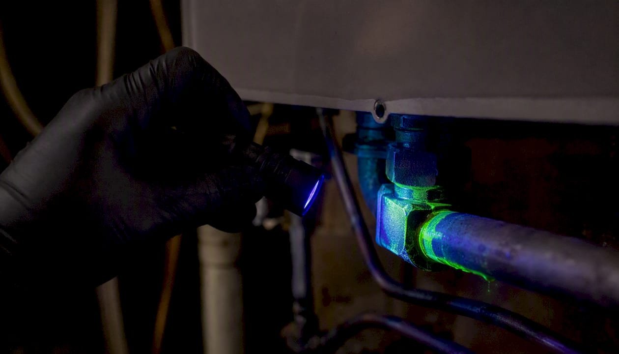
UV dye is the right call when an electronic detector narrows the area but can’t pinpoint the exact fitting, or when the leak rate is too slow for a sniffer to catch reliably. Industry guidance cautions that fluorescent dye may void some compressor warranties unless the manufacturer has approved its use — always check before injecting.
| Step | Action | Notes |
|---|---|---|
| 1. Confirm compatibility | Check OEM documentation for dye approval | Critical for newer compressors and synthetic oils |
| 2. Dose correctly | Follow the dye kit’s charge-size dosing chart | Overdosing contaminates oil and reduces heat transfer |
| 3. Inject and circulate | Run the system for the time specified (typically 15–30 min) | Longer for automotive A/C with small charge sizes |
| 4. Inspect with UV lamp | Sweep all joints, coils, and service ports in low ambient light | Dye fluoresces bright yellow-green at leak sites |
| 5. Mark and document | Tag the leak location before repair | Photo documentation supports EPA recordkeeping |
| 6. Clean up residue | Remove dye with manufacturer-approved cleaner post-repair | Prevents masking future leaks |
Numbered procedure for automotive A/C:
- Verify the dye is compatible with the vehicle’s PAG or ester oil.
- Inject the correct dose through the low-side service port using a dye injector tool.
- Run the A/C system for at least 15 minutes at normal operating conditions.
- Inspect all hose connections, the condenser, evaporator, and compressor shaft seal under a UV lamp in a shaded area.
- Document the leak site with a photo and note the discovery date.
Bubble and soap solution tests: cheap, reliable pinpointing
Soap solution is the most straightforward localization tool you have once a circuit is pressurized. Apply it after an electronic sweep confirms a general area, and it will show you the exact fitting. The RealZero guide recommends this method for confirming leak locations on pressurized joints.
- Confirm the system is pressurized to a safe working pressure — never exceed the system’s rated maximum.
- Apply soap solution generously to brazed joints, flare fittings, service valve stems, Schrader cores, and fusible plugs.
- Watch for 30–60 seconds. Slow leaks produce small, steady bubbles; fast leaks foam immediately.
- Do not apply soap solution across sight-glass manifolds during pressurization — glass can crack under uneven stress.
- After locating the leak, wipe all residue off thoroughly. Soap left on copper or aluminum fittings accelerates corrosion.
Pro Tip: Commercial leak-detection soap solutions outperform dish soap. They stay wet longer and produce finer bubbles, which matters on slow leaks where dish soap dries before a bubble forms. Keep a dedicated bottle in your kit — it costs almost nothing.
Tracer gases: finding leaks that sniffers miss
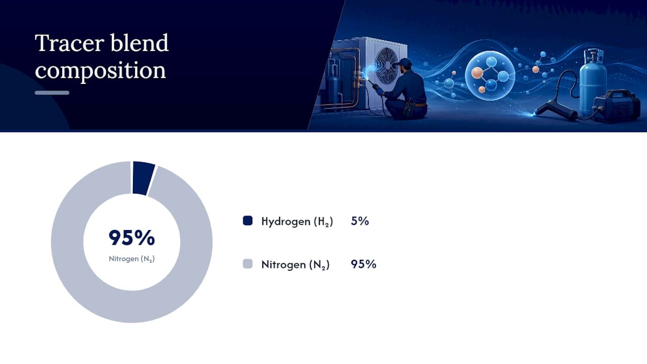
Tracer gas is the right escalation when standard electronic detectors come up empty on a concealed or micro-leak. Neither is flammable at those concentrations, and both diffuse quickly, which reduces the risk of oxygen displacement in confined spaces.
Equipment you need:
- Tracer gas cylinder (helium or 5% H₂/95% N₂ blend)
- Pressure regulator rated for the tracer gas
- Tracer-specific detector (thermal conductivity for helium; electrochemical for hydrogen blends)
- Soap solution for confirmation
Field procedure:
- Recover all refrigerant from the system per EPA requirements.
- Pressurize the system with the tracer gas blend to a safe test pressure.
- Calibrate the tracer detector against a known reference concentration before sweeping.
- Sweep slowly along joints, welds, and penetrations, starting at the highest point for hydrogen blends (hydrogen rises) and lowest for helium (helium also rises, but sweep low-to-high on enclosed spaces).
- Confirm any alarm location with soap solution before marking for repair.
- Vent the tracer gas safely and ventilate the space before re-entering for repair work.
Safety note: Work in ventilated spaces. Even non-flammable gas blends displace oxygen in confined machine rooms — use a personal gas monitor if working in enclosed areas.
Ultrasonic detectors: when sound beats gas sensing
Ultrasonic tools detect the high-frequency sound of refrigerant escaping under pressure. They work on any refrigerant type and perform best on high-pressure components like compressor discharge lines, valve seats, and high-side fittings where gas velocity is high enough to generate detectable turbulence.
- Best for: Compressor discharge side, high-pressure liquid lines, valve seats, and any area where background refrigerant vapor would trigger a chemical sensor.
- Limitations: Slow leaks on the low-pressure side generate too little turbulence to register. Sealed systems with minimal pressure differential produce no detectable signal. High ambient machinery noise (fan motors, compressors) can mask the ultrasonic signal.
- Technique: Use the directional focusing cone to isolate the signal. Sweep slowly and rotate the probe to find the direction of maximum signal strength. Background noise compensation controls help in noisy mechanical rooms.
Pro Tip: Always confirm an ultrasonic hit with soap solution before calling the leak found. Mechanical vibration from a nearby motor can mimic a leak signal, especially on thin-wall tubing.
Nitrogen pressure/decay test: the code-compliant verification method
After repair, nitrogen pressure/decay testing is the definitive verification step. 40 CFR 84.106 requires initial and follow-up verification tests for repaired leaks, with repair deadlines of generally 30 days (or 120 days where applicable). Nitrogen testing satisfies that requirement.
Step-by-step field procedure:
- Recover all refrigerant using certified recovery equipment — this is mandatory before pressurizing with nitrogen.
- Isolate the repaired section or the full circuit as appropriate.
- Connect a dry nitrogen cylinder through a two-stage regulator. Never use oxygen or compressed air.
- Pressurize to the system’s rated test pressure (typically 150–300 psig depending on system design — confirm against the equipment nameplate).
- Close the nitrogen supply valve and monitor pressure with a calibrated gauge for a minimum hold period (commonly 15–30 minutes for initial verification; longer for large-charge systems).
- A pressure drop indicates a remaining leak. Locate it with soap solution or tracer gas, repair, and retest.
- If pressure holds stable, the repair is verified.
- Document: system ID, charge size, test pressure, hold duration, technician certification number, and test result.
Required documentation fields:
- Discovery date of the original leak
- Location and nature of the leak
- Repair date and method
- Verification test type, pressure, and duration
- Technician name and EPA certification number
Pro Tip: Temperature swings during the hold period will cause pressure to drift even in a tight system — roughly 1 psig per 10°F change. Log ambient temperature at the start and end of the test so you can account for thermal drift before calling a pressure drop a leak.
Automatic leak detection systems: requirements and placement
ALD systems can substitute for periodic manual inspections when they meet EPA sensor performance criteria and are audited and calibrated on schedule. For large-charge commercial systems, this is often the most practical compliance path.
Best sensor placement locations: For example, near machine room low points and equipment involving rectangle air ducts that affect sensor siting.
- Compressor room floor level (for refrigerants heavier than air)
- Near evaporator coil drain pans
- Condenser and machine room low points
- Return air plenums in large commercial installations
Sensor types: Electrochemical sensors work well for most HFCs at ppm-level detection. IR-based fixed sensors offer longer service life and lower drift in high-humidity environments.
Pro Tip: Integrating ALD sensors with your building automation system or CMMS automates discovery-date logging and triggers repair-timeline countdowns automatically. That single integration step removes the most common compliance gap: a technician who found the leak but didn’t log the date.
Safety, refrigerant recovery, and required recordkeeping
Recovery before pressurization is mandatory for appliances covered under EPA rules, and documentation is not optional. Failing to log discovery dates, verification tests, or required inspections exposes owners and operators to civil penalties.
Safe recovery and handling checklist:
- Use EPA-certified recovery equipment and verify the recovery cylinder is within its hydrostatic test date.
- Wear safety glasses and gloves rated for refrigerant handling. Use a face shield when working with high-pressure fittings.
- Never vent refrigerant intentionally — it is illegal and subject to enforcement action.
- After recovery, verify the system is at or near atmospheric pressure before connecting nitrogen.
- Use a two-stage regulator on the nitrogen cylinder and secure the cylinder upright in a cart or bracket.
Required records to retain:
- Appliance identification and refrigerant type
- Charge size (pounds) and applicable leak-rate threshold
- Inspection dates and technician EPA certification number
- Leak discovery date, location, and repair method
- Verification test results (initial and follow-up)
- ALD audit and calibration dates if applicable
For HFC refrigerant systems at or above the 15-pound threshold, retain these records for the period specified in 40 CFR 84.106 and make them available for EPA inspection on request. Review the refrigerant SDS and TDS documents for your specific refrigerant before handling — exposure limits and first-aid procedures vary by refrigerant type.
Van-stock toolkit: what to carry on every leak call
A well-stocked truck means you can run every method in this guide without a second trip. Source refrigerant diagnostics kits and individual tools from a single supplier to simplify reorder and warranty tracking.
Essential tools:
- Heated-diode or IR electronic refrigerant detector (with spare sensor tips and filters)
- UV dye injection kit and UV lamp (with safety glasses)
- Ultrasonic leak detector with directional cone and stethoscope probe
- Tracer gas kit: cylinder, regulator, and compatible detector
- Commercial-grade soap solution (dedicated bottle, not dish soap)
- Manifold gauge set rated for your primary refrigerants
- Vacuum pump (two-stage, 5 CFM minimum for most residential/light commercial work)
- Dry nitrogen cylinder with two-stage regulator and calibrated test gauge
- Calibrated pressure/temperature chart for your refrigerants
- Inspection log forms or a CMMS mobile app for on-site documentation
Check detector calibration and battery status before every job. Swap sensor tips on a schedule, not when the detector starts missing alarms.
When you can’t find the leak: troubleshooting steps
A clean sweep with no alarm doesn’t mean no leak. It often means the leak is slow, intermittent, or in a location the probe didn’t reach.
- Check for oil stains on fittings, coils, and compressor bases — oil follows refrigerant out of any leak point.
- Verify detector calibration with a reference leak source before concluding the system is tight.
- Raise the test pressure incrementally (within rated limits) to increase leak rate and make it detectable.
- Isolate system sections by closing service valves and testing each section separately.
- Switch to tracer gas if electronic and soap methods have both failed.
- Remove suspect components for bench testing in a controlled environment if the leak remains unlocatable in the field.
- Document the discovery date regardless — the EPA repair timeline clock starts when you first identified a potential leak, not when you confirmed the location.
Pro Tip: Pull the service history before you start. A recent compressor swap or oil change can mask dye traces from a previous technician’s injection, or introduce fresh oil that looks like a new leak. Cross-check the log before chasing a ghost.
The methods that actually hold up under pressure
The guide above is technically complete. What it can’t fully convey is how often the gap between a compliant job and a callback comes down to two habits: logging the discovery date the moment you suspect a leak, and verifying the repair with nitrogen before you recharge.
Junior techs almost always skip one of those steps. They find the leak, fix it, and recharge — because the system is running and the customer is happy. But a repair that wasn’t verified with a pressure/decay test isn’t verified at all. If the system leaks again in 60 days, you have no documented baseline to show the repair held. Under 40 CFR 84.106, that gap can matter.
Train your team to treat the nitrogen test and the logbook as non-negotiable steps, not optional extras. Schedule detector calibration the same way you schedule van maintenance. And when a leak genuinely can’t be found with standard methods, escalate to tracer gas or component isolation rather than recharging and hoping. The refrigerant cost of a second call is always higher than the time cost of a thorough first one.
Stock your leak-detection toolkit through Hvac-prime
Completing a thorough leak hunt means having the right supplies on the truck before the job starts. Hvac-prime carries wholesale virgin refrigerants across the full HFC and automotive A/C range, plus professional HVAC tools including manifold gauges, vacuum pumps, and refrigerant analyzers — everything covered in the van-stock checklist above, available for direct online order with fast shipping to your shop or job site.
Contractors who stock through Hvac-prime get wholesale pricing on bulk refrigerant orders and access to bundled refrigerant diagnostics kits that include UV dye, UV lamps, and leak-detection accessories in a single order. No hunting across multiple suppliers. Browse the full catalog and place your order at Hvac-prime.
Sources
- American Innovation and Manufacturing Act: Leak Repair Requirements for Appliances Containing Hydrofluorocarbons and Certain Substitutes (EPA fact sheet)
- Ecfr
- Oxmaint
- Refrigerant leak detection methods – Facilio blog
- HVAC refrigerant leak detection: Methods and repair protocols – AirepairAuthority




 HVAC
HVAC Automotive
 Refrigerant Diagnostics Kit
 Water Heaters
2 thoughts on “Refrigerant Leak Detection Methods for HVAC & A/C Techs”