
Nitrogen Pressure Testing for HVAC: Field Guide

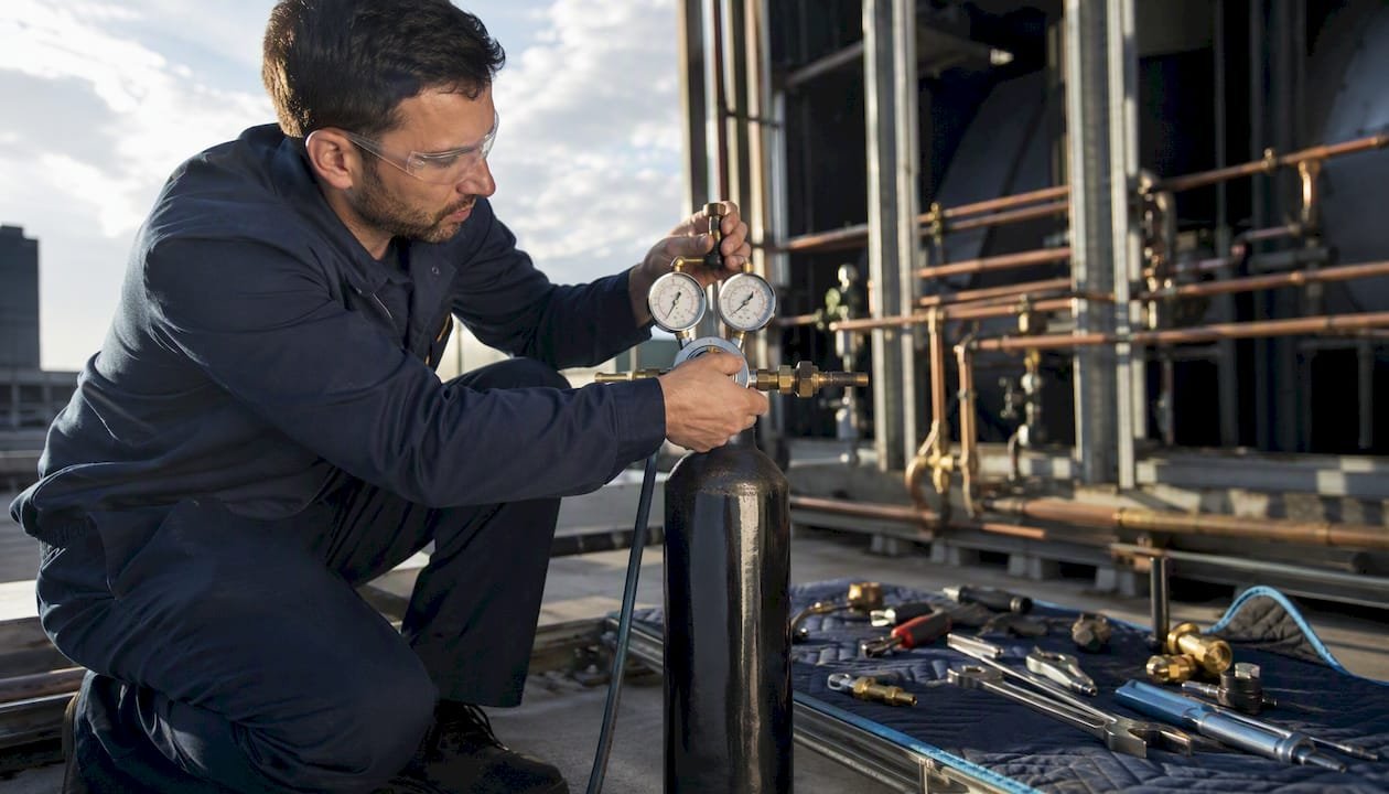
Pressurize with dry, oxygen-free nitrogen (OFN) to your specified test pressure, hold for the required duration, temperature-correct every reading, and accept the test only if the corrected pressure drop stays within your acceptance threshold. That’s the whole job. Everything else is execution.
Quick verdict:
- Pass rule (leak test): Temperature-corrected pressure drop less than 2% of test pressure over the hold period. High-consequence areas (HCA) require tighter thresholds per ASME B31.8 and 49 CFR Part 192.
- Fail action: Vent slowly, locate the leak with bubble solution or an electronic sniffer, repair with the system fully depressurized, then retest from the start.
- Key standards: ASME B31.8 (gas transmission), 49 CFR Part 192 (federal pipeline safety).
- Go-to tools: Fieldpiece digital manifolds with temperature probes, Uniweld RHP400 regulator (0–400 psi rated).
Key Takeaways
A compliant nitrogen pressure test requires OFN, a rated regulator, staged pressurization, temperature-corrected hold-period readings, and a documented pass/fail statement against the acceptance threshold.
| Point | Details |
|---|---|
| Pass/fail rule | Accept a leak test only if the temperature-corrected pressure drop is less than 2% of test pressure over the hold period. |
| Test pressure selection | Set test pressure at 1.1–1.5 × MAOP per ASME B31.8 / 49 CFR Part 192; never exceed the lowest component MAWP. |
| Temperature correction | Apply P_corrected = P_measured × (T_initial °R / T_current °R) every 15 minutes; a 10°F shift produces roughly a 2% apparent pressure change. |
| Staged pressurization | Pressurize in ~45–50 psi increments, pausing to inspect at 25%, 50%, and 75% of test pressure before reaching full test pressure. |
| Hvac-prime supply | The Uniweld RHP400 regulator, digital manifolds, and refrigerant cylinders are available through Hvac-prime for fast delivery to your job site. |
Table of Contents
- Why is nitrogen the right gas for pressure testing?
- What standards govern test pressure, hold time, and acceptance?
- How do you perform a nitrogen pressure test step by step?
- How do you calculate nitrogen volume and bottle requirements?
- Why does temperature correction matter during the hold period?
- How do you locate a leak after a pressure loss?
- What equipment and PPE do you need for a safe nitrogen test?
- What causes a test to fail and how do you diagnose it?
- What do you need to document during and after the test?
- Worked example: 100 ft of 2" ID pipe at 150 psig
- Field perspective: what experienced technicians do differently
- Get OFN, regulators, and calibrated gauges from Hvac-prime
- Sources
Why is nitrogen the right gas for pressure testing?
Nitrogen is inert, bone-dry, and non-reactive. Those three properties are what make it the default choice for pneumatic leak and pressure testing across HVAC, refrigeration, and pipeline work. GENERON’s nitrogen leak testing guidance puts it plainly: nitrogen prevents oxidation, corrosion, and moisture buildup that would otherwise contaminate a system or degrade internal components.
Compressed air carries moisture and oxygen. Moisture deposits inside copper or steel lines cause corrosion and can wreck a new refrigerant charge. Oxygen at elevated pressure is a combustion and explosion risk, especially near oil-contaminated components. Neither is acceptable for a system you’re about to charge with refrigerant.
Hydrostatic (water) testing is common in heavy pipeline work, but it’s impractical for most HVAC systems. Water is incompressible, which limits stored energy risk, but it leaves residual moisture that’s almost impossible to remove from refrigerant circuits. Nitrogen avoids all of that.
Supply options on site:
- OFN cylinders (oxygen-free nitrogen): the standard for HVAC service calls. Available in T-size (230 cu ft) and larger. Practical for single jobs.
- Nitrogen generators (PSA or membrane): cost-effective for high-volume testing at a fixed site. OnSite Gas notes that generators reduce recurring cylinder logistics, though cylinders remain more practical for field service calls.
- Small refill bottles: useful for topping off or low-volume systems, but watch the cost per cubic foot.
Purity matters. Industrial-grade nitrogen can carry trace moisture or hydrocarbons that contaminate refrigerant circuits.
What standards govern test pressure, hold time, and acceptance?
The two governing U.S. frameworks for pneumatic pressure testing are ASME B31.8 (gas transmission and distribution piping) and 49 CFR Part 192 (federal pipeline safety regulations). HVAC commissioning guides and refrigerant system standards reference these frameworks for test-factor logic, even when the specific application is a split system rather than a gas pipeline.
Test factor rules (practitioner summary):
- Strength test: 1.25–1.50 × MAOP (maximum allowable operating pressure)
- Leak test: at minimum 1.1 × MAOP
- Hold time: typically 4–8 hours for standard NPS; longer for HCA locations
HCA locations require tighter criteria. Always check the manufacturer’s MAWP (maximum allowable working pressure) on the nameplate or spec sheet — that number caps your test pressure regardless of what a generic multiplier produces.
| Test Type | Typical Test Factor | Hold Time | Acceptance Threshold |
|---|---|---|---|
| Strength test | 1.25–1.50 × MAOP | 4–8 hours minimum | No visible deformation or failure |
| Leak test | ≥ 1.1 × MAOP | 4–8 hours (HCA: longer) | < 2% temp-corrected pressure drop |
| HVAC commissioning | Per refrigerant/manufacturer MAWP | 1–8 hours (job-specific) | Zero detectable loss after correction |
Refrigerant-specific note: Test pressures vary by refrigerant. R410A high-side systems, for example, carry significantly higher MAWP than R22 systems. Airconspares’ commissioning guide recommends confirming manufacturer MAWP/PS before setting any test pressure — never assume a generic value applies to your specific equipment.
Before you set a test pressure, confirm:
- MAWP on every component in the isolated section
- The lowest-rated component sets the ceiling
- Factory-tested assemblies (e.g., OEM coils) can often be isolated and excluded from field testing
How do you perform a nitrogen pressure test step by step?
Follow this numbered checklist in order. Stop and vent if you observe unexpected pressure behavior, audible hissing, or any safety concern.
-
Review system documentation. Pull the manufacturer spec sheet, confirm MAWP for every component in the test section, and identify any assemblies that must be isolated.
-
Conduct a risk assessment. Establish a safety perimeter. Identify personnel in the area, confirm ventilation (nitrogen displaces oxygen — asphyxiation is a real hazard in enclosed spaces), and post warning signs.
-
Secure the OFN cylinder. Chain or strap it to a fixed structure. A falling cylinder can shear the valve and become a projectile.
-
Isolate the test section. Close service valves, cap open ports, and remove or bypass any pressure-relief devices rated below your test pressure. Remove Schrader cores from service ports — this dramatically speeds fill time and prevents cores from becoming leak points during the test.
-
Purge the section. Sweep the line with a low-pressure nitrogen flow (around 5–10 psig) to displace air and moisture before pressurizing. Fieldpiece recommends purging before the test as a standard pre-test step.
-
Connect the regulator and manifold. Attach the Uniweld RHP400 (or equivalent rated regulator) to the OFN cylinder via a CGA580 fitting. Connect braided hoses to the manifold and the system service port. Equalize the manifold before opening the cylinder valve.
-
Stage the pressurization. Do not go straight to test pressure. Pressurize in increments of approximately 45–50 psi (roughly 3 bar), pausing at each stage to listen for audible leaks and visually inspect joints. Fieldpiece’s guidance is explicit: staged pressurization catches catastrophic leaks early with minimal nitrogen waste. At 25%, 50%, and 75% of test pressure, stop and inspect before continuing.
-
Reach test pressure and isolate. Once at target pressure, close the cylinder valve and isolate the manifold. The system should now hold pressure on its own.
-
Allow temperature stabilization. Wait at least 15–30 minutes after reaching test pressure before starting the official hold period. Compression heats the gas; you need a stable baseline temperature reading before logging begins.
-
Monitor the hold period. Log pressure and temperature every 15 minutes. Use a calibrated digital manifold and a temperature probe placed on the pipe surface, not in ambient air.
-
Apply temperature correction. At the end of the hold period, correct the final pressure reading to the initial temperature (see the temperature correction section below). Compare the corrected drop to your acceptance threshold.
-
Locate any leaks. If the test fails, apply bubble solution to all joints, flares, valve stems, and Schrader ports. Escalate to an electronic sniffer if bubble testing doesn’t find the source.
-
Vent slowly. Open the vent valve gradually. Never rapid-vent a pressurized system — sudden depressurization can cause oil migration and component damage.
-
Proceed to evacuation. After a confirmed pass and full venting, pull the system to the required vacuum depth before charging.
Pro Tip: Equalize the manifold hoses before opening the cylinder valve. Trapped air in the hose assembly will show up as a false pressure spike and can contaminate the test section.
How do you calculate nitrogen volume and bottle requirements?
Size your nitrogen supply before you arrive on site. Running out mid-test means venting, waiting for a delivery, and restarting the hold period.
The formula:
Volume of gas required (SCF) = V_pipe (ft³) × (P_test + 14.696) / 14.696 × (520 / T_ambient °R)
Where:
- V_pipe = internal pipe volume in cubic feet
- P_test = test pressure in psig
- 14.696 psia = standard atmospheric pressure
- 520 °R = standard temperature (60°F + 460)
- T_ambient = ambient temperature in Rankine (°F + 460)
Pipe volume formula:
V_pipe (ft³) = π/4 × (ID in inches / 12)² × Length (ft)
Step-by-step worked sizing:
- Measure pipe ID and length.
- Calculate V_pipe in ft³.
- Plug into the gas volume formula above.
- Add a 20–30% safety margin for purging, hose volume, and contingencies.
- Divide total SCF by the cylinder capacity to get bottle count.
Quick-reference volume table (common line sizes, 100 ft of pipe):
*Calculations assume 60°F ambient.
A standard T-size OFN cylinder holds approximately 230 SCF at 2,015 psig. For most residential and light-commercial HVAC jobs, one cylinder is sufficient. Larger commercial runs or high test pressures may require two.
Why does temperature correction matter during the hold period?
Without correction, a passing system fails on paper, and a failing system can slip through on a warm afternoon.
Key figure: Temperature changes produce a small but significant pressure change per degree Fahrenheit at typical test pressures. A 10°F swing equals roughly a 2% apparent pressure shift — enough to flip a pass/fail decision. (Nitrogen Pressure Testing Fundamentals)
The correction formula:
P_corrected = P_measured × (T_initial °R / T_current °R)
Where temperatures are in Rankine (°F + 460).
Worked example:
- Initial conditions: 150 psig at 75°F (535 °R)
- End of hold: 147 psig at 65°F (525 °R)
- Corrected pressure: 147 × (535 / 525) = 147 × 1.019 = 149.8 psig
- Apparent drop: 3 psig (2.0%) — looks like a borderline fail
- Corrected drop: 0.2 psig (0.13%) — clear pass
Without the correction, you’d be chasing a ghost leak. The temperature fell 10°F overnight; the gas contracted; the gauge dropped. The system is tight.
Practical monitoring rules:
- Log pressure and pipe-surface temperature every 15 minutes during the hold period.
- Use a digital manifold with a clamp-on temperature probe, not an ambient thermometer. Pipe temperature lags ambient by 20–40 minutes.
- Fieldpiece Job Link tools can automate temperature compensation and logging, reducing the chance of a calculation error at the end of a long hold.
How do you locate a leak after a pressure loss?
Start with the least invasive method and escalate only when needed. Most HVAC leaks show up with bubble solution. The expensive equipment is for the ones that don’t.
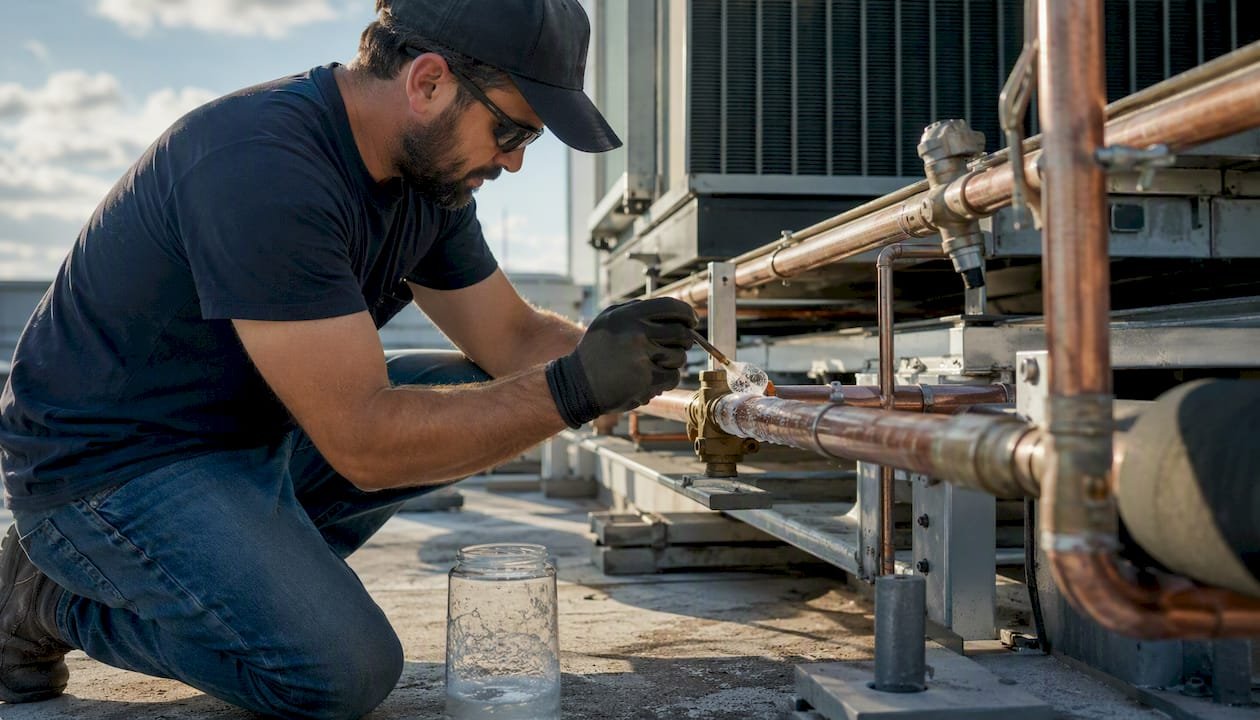
Bubble solution (Snoop or equivalent): Apply generously to every joint, flare, valve stem, and Schrader port. Watch for 30–60 seconds — slow leaks produce small, steady bubbles rather than a dramatic foam. This is your first-line method for any system above 15 psig.
Electronic refrigerant leak detectors: Useful when the system has been charged with a tracer refrigerant or when you’re testing a section that’s already had refrigerant exposure. Sensitivity varies by sensor type; heated diode and infrared sensors are the most common in HVAC work. They won’t detect nitrogen directly, but they’ll find residual refrigerant at a leak point.
Ultrasonic detectors: Pick up the high-frequency sound of gas escaping through a small orifice. Effective in noisy environments where bubble testing is impractical. Less useful for very slow leaks.
Helium tracer gas: For critical systems where bubble testing isn’t sensitive enough, Hydratight documents that helium mass spectrometry finds leak rates far smaller than any bubble test can detect. Mix a small percentage of helium into the nitrogen charge, then scan with a helium leak detector. This approach is standard in pharmaceutical, semiconductor, and safety-critical plant applications.
Isolation workflow:
- Close valves to divide the system into sections.
- Monitor each section’s pressure independently for 15–30 minutes.
- The section that drops pressure contains the leak.
- Apply bubble solution to every joint in that section.
Safety note: Never repair a joint, flare, or fitting while the system is pressurized. Vent completely before touching any connection. OFN venting should be slow and directed away from personnel and ignition sources.
What equipment and PPE do you need for a safe nitrogen test?
Arrive with the right hardware and you won’t be improvising at 150 psig.
Equipment checklist:
- OFN cylinder: Secured upright with a chain or strap. Confirm valve cap is in place during transport.
- Regulator: Rated above your test pressure. The Uniweld RHP400 delivers 0–400 psi with a CGA580 inlet and 1/4" male flare outlet — a practical choice for most HVAC test pressures. Never use a regulator with a maximum output far above your test pressure; fine pressure control at low delivery pressures is difficult on a high-range regulator.
- Braided steel hoses: Rated and tested to at least 1.5× your test pressure. Inspect for kinks, abrasion, and fitting condition before every use.
- Manifold gauge set: Use a set rated for your test pressure range. Analog gauges are acceptable, but a calibrated digital manifold gives you a direct pressure readout with better resolution.
- Calibrated digital manifold and temperature probe: Fieldpiece HVAC tools with Job Link connectivity log pressure and temperature simultaneously, which simplifies the hold-period record and the temperature correction calculation.
- Bubble solution: Snoop or equivalent. Carry enough for a full joint-by-joint inspection.
- Electronic leak detector: As a backup or for post-repair verification.
- PPE: Safety glasses (rated for the test pressure environment), hearing protection for high-pressure venting, and a face shield if working within the safety perimeter during pressurization.
- Safety barriers and signage: Rope off the test area and post nitrogen-in-use warnings.
Pro Tip: Calibration certificates for your gauges and regulators should travel with you to every job. On commissioning and warranty sign-off jobs, the documentation is reviewed — a gauge with an expired calibration certificate can invalidate the entire test record.
Confirm MAWP on every component nameplate before connecting anything. The lowest-rated component in the isolated section sets your pressure ceiling, full stop.
What causes a test to fail and how do you diagnose it?
Most failures trace back to one of five root causes: a bad braze joint, a loose flare, a defective valve or seal, a leaking Schrader core, or a component that passes at low pressure but opens at test pressure.
Diagnostic flow:
Start by verifying gauge calibration. A gauge reading 2 psig low at test pressure will produce a false failure on a tight system. If calibration checks out, apply the temperature correction. If the corrected drop still exceeds the threshold, the system has a real leak.
Isolate sections using service valves and monitor each independently. The section that drops pressure is your target. Apply bubble solution to every joint in that section, starting with the most recent work (new braze joints, flare connections, and valve replacements are the most common failure points). Check Schrader cores separately — a worn core can pass a visual inspection and still leak at pressure.
If bubble testing finds nothing and the pressure continues to drop, suspect a component that’s passing internally: a reversing valve, a solenoid, or a factory-sealed assembly. Isolate and remove the suspect component if possible, cap the ports, and retest the remaining circuit.
When to escalate:
- MAWP of a component is unknown and can’t be confirmed from documentation.
- You suspect a vessel defect (bulging, discoloration, or unusual sounds during pressurization).
- Pressure drops rapidly at low test pressure, suggesting a large failure rather than a pinhole leak.
In those cases, vent immediately, tag the system out of service, and involve a mechanical engineer or the equipment manufacturer before proceeding.
What do you need to document during and after the test?
Documentation is what turns a field test into a defensible commissioning record. Airconspares’ commissioning guide notes that documented nitrogen tests are a standard part of commissioning and compliance sign-off — and that calibration certificates for gauges are reviewed during that process.
Minimum record fields:
- Job address and system identifier
- Test date, start time, and end time
- Test section description (pipe size, length, components included)
- MAWP of the lowest-rated component
- Test pressure (psig) and test type (leak test or strength test)
- Gauge serial number and calibration certificate date
- Regulator serial number and calibration certificate date
- Pressure and temperature readings at 15-minute intervals throughout the hold period
- Temperature-corrected final pressure and calculated pressure drop (%)
- Pass/fail statement with the acceptance threshold used
- Technician name, certification, and signature
- Engineer or supervisor co-signature (required on many commercial jobs)
Presenting results:
Attach the temperature-corrected calculation as a separate sheet or appendix. Show the raw readings, the correction formula applied, and the corrected result. If the test passed, state the corrected drop as a percentage of test pressure and confirm it is within the acceptance threshold. If the test failed, note the corrected drop, the repair performed, and the retest result.
Keep calibration certificates for all gauges and regulators with the test record. On warranty or F-Gas compliance jobs, the client or inspector may request them.
Worked example: 100 ft of 2" ID pipe at 150 psig
This example ties together volume sizing, bottle sufficiency, temperature correction, and the acceptance call for a typical commercial HVAC run.
Step 1: Pipe volume
V_pipe = π/4 × (2/12)² × 100 = 0.7854 × 0.02778 × 100 = 2.182 ft³
Step 2: Gas volume required at test pressure
Assume ambient temperature of 70°F (530 °R).
SCF required = 2.182 × (150 + 14.696) / 14.696 × (520 / 530)
= 2.182 × 11.207 × 0.981
= 23.98 SCF
One standard T-size OFN cylinder (230 SCF) is more than sufficient. You have ample reserve for purging and contingencies.
Step 3: Temperature correction during the hold
Step 4: Acceptance call
Corrected pressure at end of hold: 150.1 psig
Corrected drop: 150.0 – 150.1 = –0.1 psig (the system actually gained a fraction after correction)
Without correction, this job might have triggered an unnecessary leak search.
For a downloadable formula block, copy the correction formula (P_corrected = P_measured × T_initial°R / T_current°R) into a spreadsheet with your interval readings — it takes about two minutes to set up and eliminates manual calculation errors on long hold periods.
Field perspective: what experienced technicians do differently
Small procedural choices during a nitrogen test can save hours and multiple bottles of N2. The checklist gets you compliant; these habits make you efficient.
Staged pressurization is not optional. Techs who skip straight to test pressure and then spend an hour hunting a leak at 150 psig have wasted nitrogen and time. A braze pinhole at 40 psig is easy to find. At 150 psig, it’s a spray.
Use a pipe-surface temperature probe, not an ambient thermometer. Pipe temperature lags ambient by 20–40 minutes after a temperature change. If you log ambient air temperature during the hold, your correction calculation will be wrong at the start and end of the period. Clamp the probe directly to the pipe.
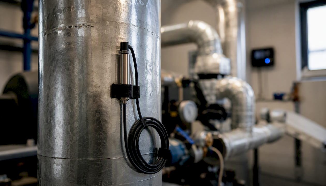
Mark your test boundaries physically. Tag every valve, cap, and isolation point with a label before pressurizing. On a multi-zone job, it’s easy to forget which section is live. A pressurized section with an unlabeled open port is a serious hazard.
Equalize the manifold before opening the cylinder valve. Trapped air in the hose assembly introduces a small but measurable error in your initial pressure reading. Open the manifold valves, let the hose volume equalize with the system, then zero your gauge reference.
Swap Schrader cores before the test, not after. Cores are a common leak point and a common source of false failures. Remove them, cap the ports with flare caps, and reinstall after the test passes. This also speeds fill time significantly on larger systems.
Vent in the right sequence. On multi-zone systems, vent the highest-pressure section last. Rapid cross-venting between sections can drive oil from one part of the circuit into another, contaminating components that were clean.
Pro Tip: If you’re testing a system that previously held refrigerant, a small amount of residual refrigerant vapor at the leak point will trigger an electronic detector even during a nitrogen test. Use that to your advantage — an electronic sniffer scan before applying bubble solution can narrow your search area fast.
Get OFN, regulators, and calibrated gauges from Hvac-prime
When you need OFN cylinders, a rated regulator, or calibrated digital tools before the next job, Hvac-prime stocks what you need and ships fast.
The Uniweld RHP400 regulator is stocked directly through Hvac-prime — 0–400 psi delivery, CGA580 inlet, 1/4" male flare outlet, ready for the pressure ranges this guide covers. Pair it with a digital manifold from the HVAC tools catalog and you have the core of a compliant, documented test setup. For refrigerant supply after the test passes, the refrigerants catalog covers R410A, R32, R454B, R1234yf, and the full range of HFC blends at wholesale pricing with fast shipping to your shop or job site. Bulk orders and contractor accounts are available — contact Hvac-prime directly to set up a wholesale account and get pricing on volume orders.
Sources
The sources below are the primary references for the standards, procedures, and methods covered in this guide.
ASME B31.8 / 49 CFR Part 192 via Midstream Calculator Engineering Guide: The essential reference for test factors, hold times, HCA requirements, and the 2% temperature-corrected acceptance threshold. Read this for compliance context on any pipeline or gas-system job.
Fieldpiece Instruments — Nitrogen Leak Testing Guide: Practical HVAC-focused guidance on staged pressurization, purging, and using digital manifolds with temperature probes for automated logging. Directly applicable to residential and commercial commissioning.
GENERON — Nitrogen Leak Test: Covers why nitrogen is preferred over air and oxygen, OFN purity requirements, and supply options including on-site generators.
Logic4Training — Good Practice Guide for Pressurizing Installed Systems: Detailed safety steps: cylinder handling, regulator selection, stepwise pressurization increments, and the rule that all repairs must be made with the system fully depressurized.
Airconspares — Nitrogen Pressure Testing for HVAC Systems: Refrigerant-specific test pressure examples and commissioning documentation requirements, including calibration certificate review during sign-off.
Hydratight — Nitrogen and Helium Leak Testing: Covers the sensitivity spectrum from bubble testing to helium mass spectrometry, with guidance on when tracer gas methods are warranted for critical systems.
- A Guide to Nitrogen Leak Testing | Fieldpiece Instruments
- Nitrogen Pressure Testing Fundamentals | Engineering Guide
- Nitrogen Leak Test – How to Pressure Test with Nitrogen Gas | GENERON
- Airconspares
- Nitrogen & Helium Leak Testing – Hydratight




 HVAC
HVAC Automotive
 Refrigerant Diagnostics Kit
 Water Heaters